Jigs and Fixtures Design Guide: Complete Engineering Principles 2026

Updated guidelines with a twist of SMED and a drop of Lean
What Are Jigs and Fixtures? Complete Engineering Design Guide
Jigs and fixtures are specialised work-holding devices used in manufacturing to accurately position, support, and secure workpieces during machining, assembly, or inspection operations. While jigs guide cutting tools, fixtures hold workpieces in precise positions without guiding tools. This comprehensive guide covers everything manufacturing engineers need to know about designing effective jigs and fixtures, incorporating lean manufacturing principles and SMED (Single-Minute Exchange of Dies) techniques.
Table of Content
- What Are Jigs and Fixtures? Key Differences Explained
- Jigs and Fixtures Design Principles: Core Considerations
- Location and Clamping Systems in Fixture Design
- Best Materials for Manufacturing Jigs and Fixtures
- Configuration – Considerations as to how the Jig/fixture should be setup
- Safety Considerations in Jigs and Fixtures Design
- Quality Output Requirements for Manufacturing Fixtures
- Modular Design Approaches for Flexible Manufacturing
- Jigs and Fixtures Cost Analysis and ROI Calculation
- SMED Principles for Quick-Change Fixture Design
- Lean Manufacturing Integration with Jigs and Fixtures
- References
What Are Jigs and Fixtures? Key Differences Explained
I wanted to focus on a core topic of manufacturing engineering where I have the most experience: designing jigs and fixtures. Rather than covering the basics of what each does, I’ve used my knowledge and experience, combined with further research, to produce what I call ‘Lean Jig & Fixture engineering design considerations’.
Understanding the fundamental difference between jigs and fixtures is crucial for any manufacturing engineer. While both are work-holding devices, jigs actively guide cutting tools during operations, whereas fixtures simply hold and position workpieces without tool guidance. This distinction determines which type of work-holding solution you need for specific manufacturing processes.
The Engineering Design Framework
Engineering design for jigs and fixtures combines three key approaches:
- Traditional design principles
- Lean manufacturing principles
- SMED principles
These form a comprehensive set of guidelines—a checklist if you prefer—that you can follow when creating your own designs. You don’t need to satisfy all criteria, just consider them and decide which are required for your specific application.
My aim is to create a practical starting point. I encourage others to get in touch if there’s anything I’ve missed.
Jigs and Fixtures Design Principles: Core Considerations
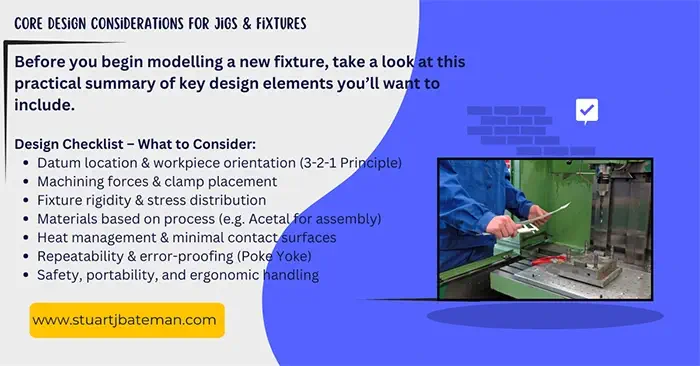
Effective jigs and fixtures design follows proven engineering principles that ensure accuracy, repeatability, and operator safety. The foundation of any successful fixture design lies in proper workpiece location, adequate clamping force distribution, and mistake-proofing features that prevent incorrect loading. These core principles form the blueprint for creating reliable work-holding solutions that enhance manufacturing efficiency.
What Can We Control with Engineering Design?
Before or after designing, consider what you can affect with your engineering design:
Process Control Points:
- Initial setup onto machine/bench
- Load/unload of workpiece
- The 6 Big Losses (setup scrap, reduced speed, production scrap, breakdowns, adjustments, slow cycles)
- Cycle time factors (choice of process, tooling used)
Key Design Considerations:
Cost considerations are essential and tie into demand and capacity—low demand and capacity typically means no need for a jig or fixture. However, calculate your ROI based on your engineering design to determine viability.
Examine the current process method: would a jig or fixture improve life for the operator and company?
Design several concepts and score them against generic and specific criteria for your product. Rank these in score order and test the most promising options.
For flexible manufacturing, work-holding devices should accommodate all parts within the family of parts.
These guidelines apply to any type of fixture or jig for manufacturing and assembly processes. Your experience will help you decide how to incorporate the relevant points below.
Location and Clamping Systems in Fixture Design
Precise workpiece location and secure clamping are the heart of effective fixture design, directly impacting part quality and manufacturing consistency. The 3-2-1 locating principle provides a systematic approach to constraining workpiece movement, while proper clamping force calculation ensures parts remain secure without distortion. Understanding these mechanical fundamentals prevents costly errors and reduces scrap rates in production.
Location Guidelines
- Locating points (datum faces) – Establish clear reference surfaces
- Workpiece orientation – Ensure consistent part positioning
- Heat considerations – If parts become hot during processing, minimise surface contact area for easier removal
- Movement restriction – Remember to restrict movement in unwanted axes
- Alignment precision – Design using dowels to fit fixture parts together when alignment is critical
- Existing features – Use pre-existing holes for internal location when available
- Cylindrical parts – Use Vee blocks to locate cylindrical workpieces
- 3-2-1 method – Three pins on the primary plane, two pins on the secondary plane perpendicular to the first, and one pin on the plane mutually perpendicular to both
Clamping Guidelines
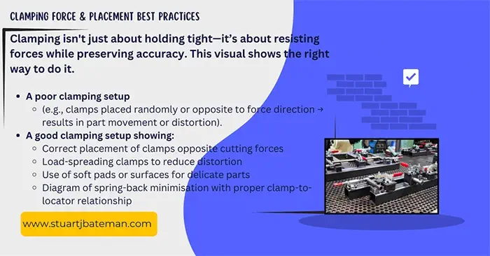
Force Management:
- Understand the direction and magnitude of forces being applied to the workpiece
- Apply sufficient clamping force to counter machining forces
- Position clamps to best resist forces from cutting tools
- Use soft surfaces when required (e.g., final assembly applications)
Operational Considerations: 5. Design clamping devices to be simple and easy to operate 6. Provide adequate clearance for workpiece variation (consider MMC conditions) 7. Understand tolerances and manufacturing stability 8. Position clamps opposite bearing points to avoid springing action 9. Calculate clamping forces and stress distributions in fixturing elements 10. Determine loads that will deform fixture or workpiece elastically or plastically 11. Spread clamping forces over large areas to minimise workpiece distortion 12. Ensure freedom from part distortion
Best Materials for Manufacturing Jigs and Fixtures
Material selection for jigs and fixtures depends on the manufacturing process, production volume, and accuracy requirements of your application. Tool steel offers superior durability for high-volume milling operations, while mild steel provides cost-effective solutions for welding fixtures, and engineered plastics work well for delicate assembly processes. The right material choice balances performance, cost, and longevity for your specific manufacturing environment.
Material Selection Guidelines
Primary Materials:
- Tool Steel – Best for milling applications requiring high wear resistance
- Mild Steel – Suitable for milling and welding fixtures, cost-effective option
- Stainless Steel – Ideal for wire EDM applications and corrosive environments
- Acetal/Plastics – Perfect for assembly operations and delicate parts
Surface Treatment:
- Hardening and tempering for wear-resistant surfaces
- Consider durability requirements based on the process and expected wear patterns
Workpiece Material Considerations:
- Maximum deformation limits
- Maximum shear stress at contact faces
- Material compatibility to prevent galvanic corrosion
Configuration – Considerations as to how the Jig/fixture should be setup
Effective jig and fixture design requires balancing multiple competing priorities to create systems that are both operationally efficient and structurally sound. The key is achieving repeatability and reliability while maintaining flexibility for different manufacturing scenarios and ensuring the design integrates seamlessly with existing machine capabilities. Successful fixtures must be robust enough to withstand production demands yet practical enough to support efficient workflows and maintenance requirements.
Design Configuration Guidelines
Core Requirements:
- Repeatability – Can your design repeat the process on every part? Is it impossible to incorrectly load the workpiece?
- Interchangeability – Can your design accommodate different parts or is it dedicated to one?
- Rigid design – Use ribs and fillets to increase rigidity
Operational Efficiency:
- Loading/unloading – Ensure ease and speed of workpiece handling
- Waste management – Consider swarf removal; allow chips to escape without building up
- Automation compatibility – Account for the machine’s extent of automation
- Machine integration – Consider the machine’s current clamping system
- Tool path clearance – Account for required tool paths; maintain low profile where needed
Maintenance and Assembly:
- Assembly ease – Design for straightforward construction
- Consumable access – Ensure easy access to parts subject to wear
- Maintenance – Design for easy cleaning, lubrication, and component replacement
- Family compatibility – Design for parts with similar features (group technology)
Specific Applications:
- Assembly fixtures – Design so parts can be built from the bottom up
- Lathe work – For prismatic parts requiring lathe work, consider mandrel requirements
- Reliability – Ensure easy maintenance and lubrication access
Resources (Internal) – Engineering Design
Liking this post? there’s more on this subject if you want to learn more:
How to use the Engineering design process
Why do engineers constantly use NDT?
Tighten tolerances and the costs go down?
How important is knowledge of materials for mechanical engineers?
You really need to apply SMED and Poka Yoke Thinking in Fixture Design
Safety Considerations in Jigs and Fixtures Design
Operator safety must be paramount in all fixture design decisions, as poorly designed work-holding devices can create hazardous working conditions and increase injury risk. Effective safety integration includes eliminating sharp edges, ensuring proper ergonomics, and incorporating features that protect operators during loading, unloading, and maintenance operations. A well-designed safety-focused fixture not only protects personnel but also reduces liability and supports sustainable manufacturing practices.
Safety Guidelines
Physical Safety:
- Eliminate sharp edges throughout the design
- Safety-critical dimensions – Ensure all safety-related measurements are clearly defined
- Fastener placement – Bolts and nuts should not protrude from the body but be placed inside recesses
Handling and Ergonomics:
4. Portability – Design for safe transportation and positioning
5. Handling aids – Design handles to make handling easier and safer
6. Weight management:
- Two-person lift required for any weight above 25kg
- Reduce weight where possible through material selection
- Use lighter materials for non-load-bearing components
- Cut holes or slots to remove material where material changes aren’t feasible
7. Ergonomic limits – Maximum 30-40lb force required to open/close clamps
Quality Output Requirements for Manufacturing Fixtures
The primary purpose of any jig or fixture is to consistently produce parts that meet specified quality requirements within acceptable tolerances and cycle times. Output considerations encompass dimensional accuracy, surface finish requirements, inspection accessibility, and the fixture’s ability to maintain precision throughout its operational life. Understanding these output parameters during the design phase ensures the fixture will deliver the manufacturing performance needed to meet production goals.
Output Guidelines
Quality Requirements:
- CTQ dimensions – Identify and control critical-to-quality dimensions
- Accuracy capability – Ensure your design can produce features within required tolerances
- Drawing requirements – Understand what’s required from engineering drawings
Performance Metrics:
- Optimal output – Balance cycle time and takt time requirements against parts produced
- Inspection integration – Consider whether workpieces need checking during the machining process
Machine Compatibility:
- Machine sizing – Account for machine size, capacity, and capabilities
- Machine accuracy – Understand the machine’s accuracy limitations and requirements
Modular Design Approaches for Flexible Manufacturing
Modular fixture design enables manufacturers to adapt quickly to changing production requirements while maximizing tooling investment returns through component reusability. By designing fixtures with interchangeable elements and standardised interfaces, manufacturers can reconfigure work-holding systems for different parts within a product family without complete redesign. This approach supports lean manufacturing principles by reducing inventory, setup times, and the total cost of tooling ownership.
Modular Guidelines
Flexibility Principles:
- Part family design – Design for families of parts with similar features
- Cassette-type systems – Use modular inserts for quick component swapping
- Dimension standardisation – Standardise overall dimensions (H/W/D) across fixture family
- Component interchangeability – Create interchangeable components serving multiple applications
- Quick-change capability – Design systems where fixtures can be changed while machines run other jobs
Jigs and Fixtures Cost Analysis and ROI Calculation
Justifying the investment in custom jigs and fixtures requires a thorough understanding of both direct costs and productivity benefits over the fixture’s lifecycle. Using proven cost calculation methods, including DeGarmo’s economic analysis framework, helps determine when fixture investment makes financial sense. This economic approach ensures that tooling decisions support business objectives while delivering measurable returns on manufacturing investments.
DeGarmo’s Cost Analysis Method
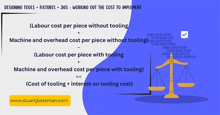
From DeGarmo’s book (page 841), here’s the engineering design equation for considering costs when developing fixtures and jigs (adjust for inflation):
Economic Justification Formula: The tooling is justified if the left-hand side equals or exceeds the right-hand value in the cost equation.
This analysis provides a quantitative method for determining when custom tooling investment makes economic sense.
SMED Principles for Quick-Change Fixture Design
Single-Minute Exchange of Dies (SMED) principles revolutionize fixture design by dramatically reducing setup and changeover times in manufacturing operations. By incorporating features like quick-release clamps, standardised mounting systems, and external setup capabilities, fixtures can be changed in minutes rather than hours. These design approaches directly impact overall equipment effectiveness and enable flexible, responsive manufacturing systems.
SMED Implementation Guidelines
Quick-Change Features:
- Spring-assisted ejection – Use springs to ease workpiece ejection
- Self-supporting design – Design so human assistance isn’t required to hold workpieces during clamping
- One-handed operation – When possible, design for single-handed operation
- Standard components – Use common sizes of materials and fasteners; avoid bespoke unless necessary
- Available materials – Use company-stocked bolts/nuts/screws when possible
Clamping Innovations:
- Boltless clamping – Examples include spring or magnetic clamping systems
- One-touch clamping – Consider how changeover processes can be reduced through design
- Cassette designs – Use modular, removable inserts for different jobs
- Quick-release mechanisms – Remember that screws/bolts only hold and release on the last and first turn
Setup Reduction Techniques:
- Self-centering jigs – Eliminate manual alignment requirements
- Alignment plates – Use permanent plates with quick-alignment features
- Setting pieces – Always eliminate the need for adjustments; use preset pieces
- Dimension standardization – Minimize setup by standardizing H/W/D dimensions
- Parallel setup – Design systems where intermediate jigs can be set up while machines run
Advanced SMED Methods:
- C-washers – One turn to loosen bolt, then slide washer out for jig removal
- Roller trolleys – Instead of cranes, use trolleys to slide jigs on/off machines
- Pear-shaped holes – Enable quick jig removal without removing bolts completely
- Engagement aids – Use radii on holes and chamfers on pins for easier engagement
Reference Methods from Shingo:
- Single motion clamping
- U-slot method
- The clamp method
- The split thread method
- The pear hole method
- U washers
Design Optimisation:
- Part count reduction – After design completion, question whether every part is needed
- Internal/external setup – Identify and move internal factors to external setup where possible
- Setup time focus – Design specifically for setup time reduction
Lean Manufacturing Integration with Jigs and Fixtures
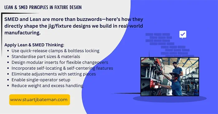
Lean manufacturing principles transform jigs and fixtures from simple work-holding devices into strategic tools for waste elimination and process optimisation. Effective fixture design reduces the seven wastes of lean manufacturing while supporting single-piece flow, standardisation, and continuous improvement initiatives. When properly designed, jigs and fixtures become enablers of lean transformation rather than obstacles to efficiency.
Lean Design Principles
Standardisation and Waste Reduction:
- Component standardisation – Standardise parts used in assembly
- Waste elimination – Eliminate/reduce waste in both design and process
- Reduce variation
- Reduce complexity
- Reduce mistakes through poka-yoke
Flow and Timing:
3. Takt time consideration – Determine if assembly use increases or decreases current takt time
4. Single-piece flow – Move design toward single-piece flow concepts
5. Constraint analysis – Consider if your design will create process constraints
Workplace Organization:
6. 5S integration – Organise workplace considerations:
- Storage of assembly
- Transportation of assembly
- Identification methods
Performance Improvement:
7. Lead time reduction – Will this engineering design affect current lead time?
8. Demand analysis – Is takt time too short for manual operations, justifying jig/fixture use?
9. Operation minimization – Minimise steps/operations required in design and process
Error Prevention:
10. Misalignment detection – Design to highlight workpiece misalignment (poka-yoke)
11. Flow integration – Design jigs incorporating flow concepts – Example: For parts requiring three operations (machining different sides), position all three locations on the same jig and program to machine all operations in sequence.
Continuous Improvement
Remember that these engineering design considerations will be used throughout the jig/fixture lifecycle. With each iteration, return to these guidelines to consider necessary modifications. Compromise is inevitable in jigs and fixtures design, but systematic consideration of these principles will lead to better outcomes.
References
- DeGarmo et al “Materials and Processes in Manufacturing” – 1988
- Shingo ”A revolution in manufacturing: The SMED system”
- “An application of SMED technology” – Berna Ulutas 2017
- “Rethinking modular Jigs’ design regarding the optimization of machining times” – S.Kumar et al 2019
- “Design and Analysis of Jigs and Fixtures for manufacturing process” – H.Radhwan et al 2019
- “The design and need for Jigs and Fixtures in Manufacturing” – Charles Chikwendu Okpala et al 2015
- “A literature survey of fixture-design automation” – J.C Trappey and C.R Liu 1990
- “The design of everyday things” – Don Norman
Twenty principles of jig and fixture design – From DeGarmo p.821
- Determine the critical surfaces or points for the part
- Decide on locating points and clamping arrangements
- For mating parts, use corresponding locating points or surfaces to ensure proper alignment when assembled
- Try to use 3-2-1 location, with 3 assigned to largest surface. Additional points should be adjustable
- Locating points should be visible so that the operator can see if they are clean. Can they be replaced if worn?
- Provide clamps that are as quick acting and easy to use as is economically justifiable
- Clamps should not require undue force by the operator to close or to open, nor should they harm hands or fingers during use
- Clamps should be integral parts of device. Avoid loose parts that can get lost
- Avoid complicated clamping arrangements or combinations that can wear out or malfunction
- Locate clamps opposite locators (if possible) to avoid deflection/distortion during machining and spring back afterwards
- Take the thrust of the cutting forces on the locators (if possible) and not on the clamps
- Arrange the work holder so that the workpiece can easily be loaded and unloaded from the device and so that it can be loaded in the correct manner (mistake proof) and in such a way that the location can be found quickly
- Consistent with strength and rigidity, make the work holder as light as possible
- Provide ample room for chip clearance and removal
- Provide accessibility for cleaning
- Provide for entrance and exit of cutting fluid (which may carry off chips) if one is to be used
- Provide four feet on all movable work holders
- Provide hold down lugs on all fixed work holders
- Provide keys to align fixtures on machine tables
- Do not sacrifice safety for production
Resources (External) – Engineering Design
Here is a list of resources I find particularly usage in any design project I’m doing:
GD and T Basics – A one stop shop to list and understand all the Geometric tolerances used today in industry, with simple explanations (some are long) with illustrations to demonstrate.
Learn Mech – As it says on the tin, head over here to dive into the many different mechanical examples shown and explained on this site.
My Physics Lab – A great interactive website that teaches you many (if not all) the mechanical principles and physics.
Engineering Toolbox – A true repository of engineering (all fields) knowledge, go jump down that rabbit hole!
Engineers Edge – Just like the Engineering toolbox, this site has calculators for many of the engineering principles it talks about, great to working out things.


What are your thoughts? Have I covered everything or is there more you know and would like to share?
I’m always learning and improving this site and my blogs, so please feel free to get in touch with me via LinkedIn or this site to discuss any topics I have covered.
If you’re having trouble finding ways to progress check out these sites filled with free learning tools:


Discover more from The Chartered Engineer
Subscribe to get the latest posts sent to your email.
